High Dynamic Range (HDR)
If an image is too dark or too bright, details and fine nuances are difficult to see. Cameras with a high dynamic range (HDR) can be used to overcome this problem. They can capture objects in detail even in difficult lighting conditions. Such cameras are particularly suitable for applications with extreme lighting fluctuations or very strong point light sources in whose surroundings objects are to be detected. Extreme brightness fluctuations are known, for example, from driver assistance systems or from process control during laser welding.
The dynamic range of a camera is described by the ratio of the maximum and minimum intensity that a camera can detect. The maximum detectable intensity is determined by the full-well capacity (FWC), which is defined by the maximum absorbable load of the pixel before saturation. The minimum detectable intensity with a camera is limited by different noise emissions. A distinction must be made between electronic noise and the noise of the light. At very low intensities the readout noise and at long integration times the dark current noise of the used image sensor can limit the performance. In addition to the dynamic range, the signal-to-noise ratio (SNR) is another important variable for the specification of image processing systems. Especially in optical metrology, a high signal-to-noise ratio is essential. Due to the nature of light, this can only be achieved with measurements at high intensities and with sensors with a correspondingly high full-well capacity. The SNR is equal to the root of the full-well capacity, whereas other noise sources can be neglected. The performance of cameras and image sensors is measured using the measurement methods defined in the EMVA1288 standard. This standard also defines the essential parameters.
Various methods are used to extend the dynamic range of a camera and to obtain detailed images even in light conditions that are difficult to control.
LinLog® Technology
A hardware-based approach to extending the dynamic range is the LinLog® technology developed by Photonfocus. The dynamic extension is realized in the pixel. The development was preceded by the implementation of CMOS image sensors with logarithmic response curve. These sensors have three major disadvantages in image processing systems: the lack of a global shutter, the massive luminescence and the temperature dependence of the sensor output signal.
With the LinLog® technology developed by Photonfocus, these drawbacks are overcome by a combined linear-logarithmic sensor response curve (LinLog® response curve) by linking the integrating global shutter pixel with the logarithmic pixel via pixel control.
In the low light region, the response of the detector is linear. This gives a very good grey scale resolution in this range. High intensities are compressed due to the logarithmic properties of the pixel in bright conditions. The onset of the logarithmic compression and the strength of the compression can be adjusted with the help of several LinLog® parameters. These parameters can be adjusted by the customer in software, allowing an optimal adaption to the application. The figure above gives an insight into the possibilities to adjust the response curve offered by Photonfocus LinLog® cameras.
LinLog® response curve of the CMOS camera MV-D1024E at various LinLog® settings
The sensors can be operated with a fully linear response curve or the LinLog response curve. In addition to the response curve control, the Photonfocus image sensors are also equipped with a very high full-well capacity, which makes them ideal for applications in optical metrology.
The Photonfocus CMOS cameras not only offer the advantage of a wide dynamic range, but it is also possible to perfectly adapt the resolution and speed of the camera to the process control by selecting the appropriate readout window (ROI, Region of Interest).
The LinLog® response curve can, for example, be used advantageously for combined 2D/3D inspection procedures. The structure of the welding seam and surrounding material is inspected in the linear region of the detector response curve. The laser line for the triangulation is captured in the logarithmic range. This enables a reliable detection of the line in bright regions where reflections from metal are strong and in more weakly reflecting zones of the welding seam without losing the laser line used for the profilometry.
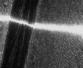 | 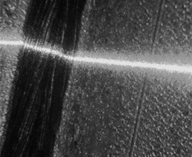 |
| Standard CMOS camera with linear response curve (<60dB) | Photonfocus CMOS camera with LinLog® response curve (<120dB) |
The figure above shows an example of a combined 2D/3D inspection for the quality control of laser welding seams. The structure of the weld seam and the surrounding material is checked in the linear range of the detector response curve, while the laser line for triangulation is measured in the logarithmic range. This enables the visibility of the laser line both in highly reflective and in less reflective areas of the weld seam.
Photonfocus offers you a wide range of different cameras with LinLog® technology.
Find the right camera for your application here.
Multiple exposures
Another frequently used method is to increase the dynamic range by combining image information from differently exposed images. In smartphones, several images of an exposure series are used for image synthesis. In industrial image processing, this method is usually limited to 2 images, as high frame rates are often required in image processing systems.
On the one hand, images with short and long exposure times can be taken and calculated alternately with the help of sequencers. This method has the advantage of a high spatial resolution, but with fast processes the problem of motion blur. On the other hand, image sensors can be constructed with combed exposure time controls for rows or columns, which allow the simultaneous acquisition of images with short and long exposure times in favor of a reduced spatial resolution. The user thus has the choice between low motion blur or high spatial resolution when designing the image processing system.
Photonfocus image sensors can be operated in both modes. An example of an image reconstruction from images with combed lines of different exposure times is shown in the following illustrations.
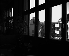 |  |
| Short exposure | Long exposure |
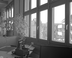 | ||
| Processed HDR image |
Read more about the Photonfocus Cameras which support multiple exposures.
2 readout notes in pixel
In the pixels and the sensor architecture of ultra-low light sensors (sCMOS sensors), modules are implemented that allow the reading of pixel information at different internal gain factors. This information can also be used to obtain high dynamic images.
Get to know our ultra-low light cameras here.
Non-destructive readout
The increase of the dynamic range by multiple readout of the image (Non-Destructive Readout (NDRO)) during the exposure time is known from scientific applications. Standard CMOS image sensors usually do not support this operating mode, since the pixel matrix control automatically resets the pixels after a readout process. This operating mode can be implemented by the extremely flexible control in the Photonfocus image sensors. Further information can be provided on request.
Contact us at info(at)photonfocus.com.


